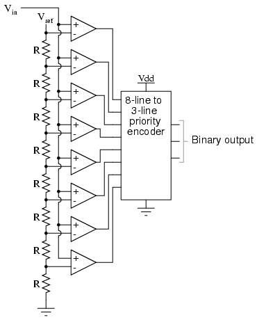

- #Analog to digital converter reference voltage generator
- #Analog to digital converter reference voltage full
- #Analog to digital converter reference voltage code
- #Analog to digital converter reference voltage plus
The SAR ADC of claim 6, wherein the SAR logic is configured to cause the DAC to generate the first voltage such that the first voltage is equal to the analog input voltage, wherein while the first voltage is generated, the switches of the DAC are connected to the ground voltage and the second voltage is a lesser of first and second voltage options.Ĩ. The SAR ADC of claim 5, wherein the DAC comprises a plurality of capacitors and a plurality of switches, wherein each of the switches is connected to a particular one of the capacitors, is selectively connected to either of a ground voltage and a reference voltage, and is configured to selectively connect the particular capacitor to either of the ground voltage and the reference voltage.ħ.
#Analog to digital converter reference voltage plus
The SAR ADC of claim 1, wherein the first voltage is substantially equal to the analog input voltage plus a voltage determined by the digital input word.Ħ. The SAR ADC of claim 1, wherein the SAR logic is configured to determine whether the digital input word causes the DAC to generate the first voltage such that the first voltage is greater than or is less than the analog input voltage based on whether the analog input voltage is determined to be less than or greater than a reference voltage by the comparator.ĥ. The SAR ADC of claim 1, wherein the SAR logic is configured to determine an MSB of a digital output word by comparing the analog input voltage with a reference voltage.Ĥ.
#Analog to digital converter reference voltage generator
The SAR ADC of claim 1, wherein the voltage reference generator is configured to select the second voltage based at least in part on whether the analog input voltage is greater than a reference voltage.ģ. A successive approximation register (SAR) analog to digital converter (ADC), comprising: a SAR logic circuit configured to generate a digital input word a DAC, configured to receive the digital input word and an analog input voltage, and to generate a first voltage based on the analog input voltage and the digital input word a comparator, comprising: a first input terminal configured to receive the first voltage, and a second input terminal configured to receive a second voltage, wherein the comparator is configured to generate a comparator output voltage based on the first and second voltages, wherein the comparator output voltage has a value corresponding with a sign of a difference between the first and second voltages and a voltage reference generator, configured to generate the second voltage by selecting the second voltage from a plurality of discrete voltage options, wherein the SAR logic circuit is further configured to receive the comparator output voltage, and to generate the digital input word for the DAC based on one or more comparator output voltages received from the comparator.Ģ. The rate of new values is called the "sampling rate" or " sampling frequency" of the converter.1. It is therefore required to define the rate at which new digital values are sampled from the analog signal. The analog signal is continuous in time and it is necessary to convert this to a flow of digital values. One should consider taking this phenomenon into account before choosing an ADC.

This table shows, for example, that it is not worth using a precise 24-bit ADC for sound recording if we don't have an "ultra low jitter" clock.
#Analog to digital converter reference voltage full
:E FSR is the full scale voltage range = V_, where q is a number of ADC bits. Where::Q is resolution in volts per step (volts per output code), The voltage resolution of an ADC is equal to its overall voltage measurement range divided by the number of discrete intervals as in the formula: Resolution can also be defined electrically, and expressed in volts. signed integer), depending on the application. unsigned integer) or from -128 to 127 (i.e. The values can represent the ranges from 0 to 255 (i.e. For example, an ADC with a resolution of 8 bits can encode an analog input to one in 256 different levels, since 2^8 = 256.

In consequence, the number of discrete values available, or "levels", is usually a power of two. The values are usually stored electronically in binary form, so the resolution is usually expressed in bits. The resolution of the converter indicates the number of discrete values it can produce over the range of analog values. However, some non-electronic or only partially electronic devices, such as rotary encoders, can also be considered ADCs.
#Analog to digital converter reference voltage code
The digital output may be using different coding schemes, such as binary, Gray code or two's complement binary. Typically, an ADC is an electronic device that converts an input analog voltage (or current) to a digital number. The reverse operation is performed by a digital-to-analog converter ( DAC). An analog-to-digital converter (abbreviated ADC, A/D or A to D) is an electronic integrated circuit, which converts continuous signals to discrete digital numbers.


 0 kommentar(er)
